
HP VSR1000: How to configure a IPsec tunnel
One possible use case for the HP VSR1000 is to build IPsec tunnels for secure data transfer. In this post I will show you how to configure a IPsec tunnel between two HP VSR1000. If you need a short introduction, feel free to take a look at this article.
The experimental setup
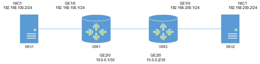
We have two server VMs (in this case Windows Server 2008 R2 with SP1) and two HP VSR1000 Virtual Service Router. To simplify I added a vSwitch without uplinks to my ESXi at home. This vSwitch has three port groups. While each VSR1000 is connected to only one site and the WAN port group, the server VMs are only connected to one site. The WAN port group should simulate the WAN link, but in reality WAN can be anything. This is a screenshot of the ESXi vSwitch and port group configuration, as well as the logical setup.
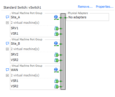
Patrick Terlisten/ vcloudnine.de/ Creative Commons CC0
Patrick Terlisten/ vcloudnine.de/ Creative Commons CC0
Site A uses the subnet 192.168.100.0/24. Site B uses the subnet 192.168.200.0/24. The subnet 10.0.0.0/30 is used on the WAN side. The ip addressing looks like this:
| Site A | IP Address |
|---|---|
| VSR1 | 192.168.100.1/24 |
| SRV1 | 192.168.100.2/24 |
| Site B | IP Address |
|---|---|
| VSR2 | 192.168.200.1/24 |
| SRV2 | 192.168.200.2/24 |
| WAN | IP Address |
|---|---|
| VSR1 | 10.0.0.1/30 |
| VSR2 | 10.0.0.2/30 |
The VSR1000 uses HP Comware 7.1, so it’s possible that the IPsec configuration differs from Comware 5.
The configuration
I’ve described the initial configuration of a VSR in this article. So in this article I focus on the configuration of the IPsec tunnel itself. First of all we need to configure the interfaces. On VSR1 (the first router):
[VSR1]interface GigabitEthernet1/0
[VSR1-GigabitEthernet1/0]ip address 192.168.100.1 24
[VSR1-GigabitEthernet1/0]description LAN Site A
[VSR1-GigabitEthernet1/0]interface GigabitEthernet2/0
[VSR1-GigabitEthernet2/0]ip address 10.0.0.1 30
[VSR1-GigabitEthernet2/0]description WAN
[VSR1-GigabitEthernet2/0]quit
And on VSR2 (the second router)
[VSR2]interface GigabitEthernet1/0
[VSR2-GigabitEthernet1/0]ip address 192.168.200.1 24
[VSR2-GigabitEthernet1/0]description LAN Site B
[VSR2-GigabitEthernet1/0]interface GigabitEthernet2/0
[VSR2-GigabitEthernet2/0]ip address 10.0.0.2 30
[VSR2-GigabitEthernet2/0]description WAN
[VSR2-GigabitEthernet2/0]quit
Sure, we could setup a small single area OSPF, but for now a static routing is sufficient. These two routes allow us to reach the other side. There is currently no default route (gateway of last resort). On VSR1:
[VSR1]ip route 192.168.200.0 24 10.0.0.2
And on VSR2:
[VSR2]ip route 192.168.100.0 24 10.0.0.1
I will show you how to configure a ACL-based IPsec tunnel. This happens in three steps:
- Create an ACL
- Create a IPsec policy
- Apply the policy to an interface
The first step is to configure ACLs. These ACLs are used to determine what kind of traffic should be protected. The ACL number 3000 determines, that this is an advanced ACL (ACL number 3000 - 3999). The ACL consists of multiple rules, in this case two rules and a comment. The rules define, that every traffic from 192.168.100.0/24 to 192.168.200.0/24 (and vice versa) should be permitted. All other traffic will be denied. On VSR1:
[VSR1]acl number 3000
[VSR1-acl-adv-3000]rule 0 permit ip source 192.168.100.0 0.0.0.255 destination 192.168.200.0 0.0.0.255
[VSR1-acl-adv-3000]rule 1 deny ip
[VSR1-acl-adv-3000]description IPsec ACL
[VSR1-acl-adv-3000]quit
And on VSR2:
[VSR2]acl number 3000
[VSR2-acl-adv-3000]rule 0 permit ip source 192.168.200.0 0.0.0.255 destination 192.168.100.0 0.0.0.255
[VSR2-acl-adv-3000]rule 1 deny ip
[VSR2-acl-adv-3000]description IPsec ACL
[VSR2-acl-adv-3000]quit
The next steps are to configure the transform set, the keychain, an IKE profile and an IPsec policy. The transform set is part of the IPsec policy and defines the security parameters for the IPsec SA negotiation. This includes the security protocol (AH, ESP), the encapsulation mode and the encryption and authentication algorithms. Because this is a site-2-site VPN the encapsulation mode “tunnel” is used. On VSR1:
[VSR1]ipsec transform-set ts1
[VSR1-ipsec-transform-set-ts1]encapsulation-mode tunnel
[VSR1-ipsec-transform-set-ts1]protocol esp
[VSR1-ipsec-transform-set-ts1]esp encryption-algorithm aes-cbc-256
[VSR1-ipsec-transform-set-ts1]esp authentication-algorithm sha1
[VSR1-ipsec-transform-set-ts1]quit
An on VSR2:
[VSR2]ipsec transform-set ts1
[VSR2-ipsec-transform-set-ts1]encapsulation-mode tunnel
[VSR2-ipsec-transform-set-ts1]protocol esp
[VSR2-ipsec-transform-set-ts1]esp encryption-algorithm aes-cbc-256
[VSR2-ipsec-transform-set-ts1]esp authentication-algorithm sha1
[VSR2-ipsec-transform-set-ts1]quit
Now the keychain is configured. The keychain includes the pre-shared key. On VSR1:
[VSR1]ike keychain keychain_vsr1
[VSR1-ike-keychain-keychain_vsr1]pre-shared-key address 10.0.0.2 30 key simple VPN-Passw0rd
[VSR1-ike-keychain-keychain_vsr1]quit
And on VSR2:
[VSR2]ike keychain keychain_vsr2
[VSR2-ike-keychain-keychain_vsr2]pre-shared-key address 10.0.0.1 30 key simple VPN-Passw0rd
[VSR2-ike-keychain-keychain_vsr2]quit
The pre-shared key is displayed encrypted in the configuration, even if it’s entered here in plain text format. The next step is to configure the IKE profile. In this example it’s simply called “1”. You can give it another name if you like. The IKE profile links the identity of the remote VSR and the keychain. On VSR1:
[VSR1]ike profile 1
[VSR1-ike-profile-1]keychain keychain_vsr1
[VSR1-ike-profile-1]match remote identity address 10.0.0.2 30
[VSR1-ike-profile-1]quit
And on VSR2:
[VSR2]ike profile 1
[VSR2-ike-profile-1]keychain keychain_vsr2
[VSR2-ike-profile-1]match remote identity address 10.0.0.1 30
[VSR1-ike-profile-1]quit
Now the second step (creating an IPsec policy) comes to an end. The IPsec policy links the transform set, the IKE profle and the ACL together. The 10 is the sequence number. You can choose another sequence number if you like. You can also choose another name. I named my policy “policy1”. On VSR1:
[VSR1]ipsec policy policy1 10 isakmp
[VSR1-ipsec-policy-isakmp-policy1-10]security acl 3000
[VSR1-ipsec-policy-isakmp-policy1-10]transform-set ts1
[VSR1-ipsec-policy-isakmp-policy1-10]local-address 10.0.0.1
[VSR1-ipsec-policy-isakmp-policy1-10]remote-address 10.0.0.2
[VSR1-ipsec-policy-isakmp-policy1-10]ike-profile 1
[VSR1-ipsec-policy-isakmp-policy1-10]quit
And on VSR2:
[VSR2]ipsec policy policy1 10 isakmp
[VSR2-ipsec-policy-isakmp-policy1-10]security acl 3000
[VSR2-ipsec-policy-isakmp-policy1-10]transform-set ts1
[VSR2-ipsec-policy-isakmp-policy1-10]local-address 10.0.0.2
[VSR2-ipsec-policy-isakmp-policy1-10]remote-address 10.0.0.1
[VSR2-ipsec-policy-isakmp-policy1-10]ike-profile 1
[VSR2-ipsec-policy-isakmp-policy1-10]quit
The last step is to apply the IPsec policy to an interface. On VSR1:
[VSR1]interface GigabitEthernet2/0
[VSR1-GigabitEthernet2/0]ipsec apply policy policy1
[VSR1-GigabitEthernet2/0]quit
And on VSR2:
[VSR2]interface GigabitEthernet2/0
[VSR2-GigabitEthernet2/0]ipsec apply policy policy1
[VSR2-GigabitEthernet2/0]quit
The result
Once the traffic comes, the IPsec tunnel is established. You can verify this with this command:
[VSR1]display ipsec sa
-------------------------------
Interface: GigabitEthernet2/0
-------------------------------

  -----------------------------
  IPsec policy: policy1
  Sequence number: 10
  Mode: isakmp
  -----------------------------
    Tunnel id: 0
    Encapsulation mode: tunnel
    Perfect forward secrecy:
    Path MTU: 1427
    Tunnel:
        local  address: 10.0.0.1
        remote address: 10.0.0.2
    Flow:
    sour addr: 192.168.100.0/255.255.255.0  port: 0  protocol: ip
    dest addr: 192.168.200.0/255.255.255.0  port: 0  protocol: ip

    [Inbound ESP SAs]
      SPI: 949311587 (0x38955863)
      Transform set: ESP-ENCRYPT-AES-CBC-256 ESP-AUTH-SHA1
      SA duration (kilobytes/sec): 1843200/3600
      SA remaining duration (kilobytes/sec): 1843199/301
      Max received sequence-number: 16
      Anti-replay check enable: Y
      Anti-replay window size: 64
      UDP encapsulation used for NAT traversal: N
      Status: active

      [Outbound ESP SAs]
      SPI: 3361053318 (0xc8559a86)
      Transform set: ESP-ENCRYPT-AES-CBC-256 ESP-AUTH-SHA1
      SA duration (kilobytes/sec): 1843200/3600
      SA remaining duration (kilobytes/sec): 1843199/301
      Max sent sequence-number: 16
      UDP encapsulation used for NAT traversal: N
      Status: active
That’s it! :) If you are looking for more, take a look into the HP VSR1000 configuration guides. This is a 18 MB (!) PDF which covers all aspects of the VSR1000 and it includes a lot of configuration examples.